Avoiding Damage by Eliminating Ground Bounce in Test Fixtures
Introduction
Applying power to the device under test (DUT) may seem the most trivial part of a test setup, but effects like ground bounce can damage other hardware connected to the jig, such as an XJLink JTAG controller.
This application note explains how this problem can arise in even the simplest of setups and suggests some ways it can be resolved.
Inrush Currents Causing Ground Movements
Figure 1 shows a typical test setup. In this example, an external 24 V supply is connected to the mains and powers the test fixture containing the DUT. Because part of the test procedure uses JTAG, an XJLink is also used, which is connected to a mains-powered PC via a USB cable.
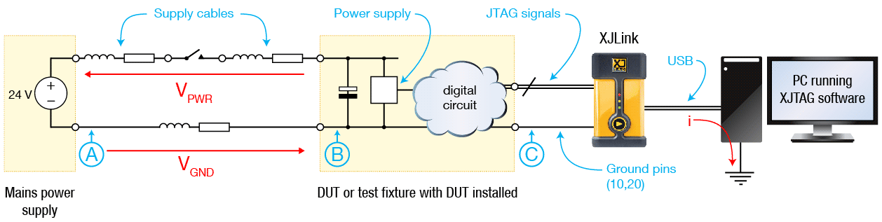
Figure 1 – Typical Test Setup with DUT and XJLink connections
With the test setup powered down, the input capacitors across the test fixture’s supply rail are fully discharged. When power is applied, those capacitors can cause a large inrush current to flow that’s much greater than the steady-state current normally drawn from the supply.
Those capacitors cannot charge instantaneously, and the voltage across them will therefore be zero at the moment the power switch is closed. That means 24 V is briefly being dropped across the cables’ impedances and resistances (VPWR and VGND in the diagram). If we assume the leads have equal diameter and that the total lengths in positive and negative are the same, VPWR and VGND will be similar.
At the instant the switch is closed, the potential at point B will therefore briefly be significantly higher than at A. If point A has been connected to external ground, this would make point B spike to 12 V. This means the local “ground” potential of the DUT and consequently also the ground pins on the XJLink’s JTAG connector (point C) will momentarily be raised above external ground. Because of the USB cable joining the XJLink to the mains-powered PC, this causes a flow of current to the external ground through the XJLink via the USB cable.
This brief current flow can exceed the maximum limit on the XJLink’s pins and cause damage.
While the effect of this ground bounce is most obvious on the XJLink’s ground pins, it can also affect others pins: when the DUT’s local ground becomes significantly higher than the PC’s ground, the pins of the devices in the DUT will also shift and can become another path for unexpected and potentially damaging current.
Mitigating the Problems Caused by Ground Bounce
There are several approaches that could help to prevent these problems:
- Provide a soft-start circuit. A soft-start circuit in the power feed will limit the rate at which the voltage rises in the fixture, thereby reducing the inrush current. This will keep VGND and VPWR to a minimum.
- Use a mains power supply with a floating output and do not tie point A to ground. The inrush current will obviously still occur, but in this case, the fixture’s ground will not become elevated. Point A will spike negative at the moment the switch is closed but this should not be a problem provided the mains power supply being used has a true floating output.
It should be noted that the power supply’s output must not have any AC path back to the mains supply—some cheap AC adapters have been found to have light AC coupling to the live mains terminal, which can reintroduce the link to ground at point A.
- Tie the power supply’s ground to the test fixture instead of its negative output. Referring back to figure 1, if point B is connected to ground via a short, thick ground strap, and point A is allowed to float, no significant voltage difference can be generated across the XJLink, and the potentially damaging current will not flow. Again, a power supply with a truly floating output must be used.
To provide an earth connection for the jig, you can connect a low impedance lead from the power supply’s GND terminal to the test fixture but not to the supply’s negative output (because the output must remain floating).
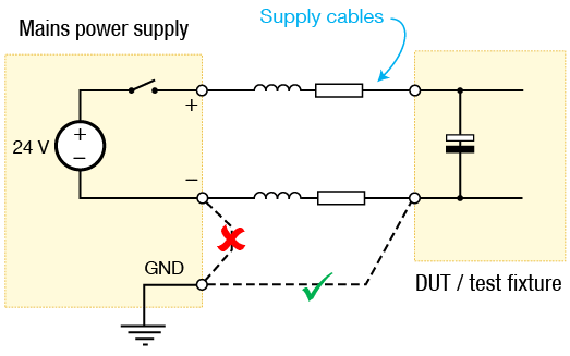
Figure 2 – Grounding a Test Fixture
- Ensure the ground wire has much lower impedance than the positive lead. This will ensure VGND is lower than VPWR and so reduces the potential difference between the XJLink’s pins and the external ground.
This can be achieved in two ways:
- Ensure the ground connection has larger diameter than the positive and, if practical, is shorter.
- Place a ferrite on the positive lead (but not the negative). This will increase the impedance to the current spike in the positive connection and therefore ensure more of the voltage drop occurs across the positive lead rather than the negative.