Find Out How a Leading Electronic Design Company Shaves Weeks Off Debug and Testing

Image of CEO of XJTAG Simon Payne Simon Payne, CEO, XJTAG |  Subscribe to LinkedIn newsletter

XJTAG Testing Times - Psychedelic FPGA

When deadlines are tight and designs are complex, every hour saved in debugging counts. That’s exactly what one advanced RF technology product developer achieved a faster time to market by adopting smart testing to speed up development, improve coverage, and streamline production.

The Challenge

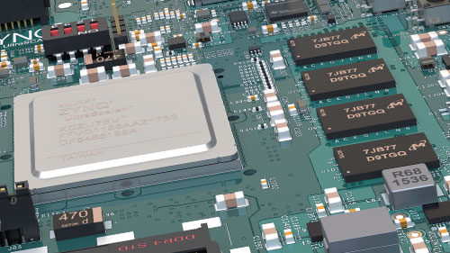
The company develops cutting-edge spectral analysis products used for real-time spectrum monitoring across multiple industry sectors. Their advanced system, built around a Xilinx FPGA, surveys a wide frequency range to map and manage radio spectrum usage.

But behind the innovation came complexity. Each of their advanced RF system boards featured a high pin-count FPGA, a nightmare for traditional testing. Probing those densely packed BGAs wasn’t just time-consuming; it was next to impossible.

The Turning Point

That’s when the company turned to smart testing. The switch changed everything.

Their engineers could test the Xilinx FPGA (a JTAG enabled device) and extend the testing to non-JTAG devices on their board by using advanced boundary scan, achieving over 80% device coverage across the their boards, all without complex test fixtures. Tests that once took weeks to validate could now be completed in a fraction of the time.

Why It Works

Boundary-scan testing, defined by IEEE 1149.x, allows engineers to validate connections and functionality without physically probing every device pin. This can then be taken further with an intuitive development environment, making it easier to write, reuse, and share tests across multiple boards and projects.

By testing from the device’s perspective, the company could reuse test scripts between modules, saving engineering time and ensuring consistency. And by visualising results and isolating faults development became faster than ever.

The Results

  • Weeks of debugging reduced to days
  • 80%+ device coverage achieved via advanced boundary scan
  • Reusable tests across multiple products and projects
  • Simplified production testing through reusable test harnesses

The company now uses advanced boundary scan across the entire product lifecycle from design and development to contract manufacturing, ensuring every board leaving production meets the highest standard of reliability.


See how this world leading company is accelerating their design and testing using advanced boundary scan. Read the case study here.

Or explore more success stories, click here to see over 100 case studies.

Is it time to try XJTAG for free with your own board and see how much faster you can debug, test, and program your designs?
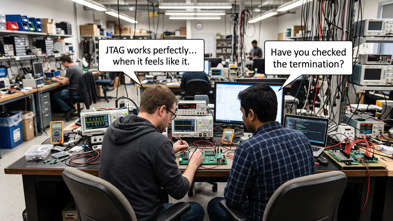
Testing Times - PCB engineers in workshop, discussing JTAG termination
You’ve Routed Out JTAG. Now Make Sure It Actually Works Last week, we looked at the importance of making the JTAG capability inside your FPGA, processor or SoC accessible on the PCB. But routing the signals out is only part of the job. Once you've provided access, you also need to make sure the JTAG interface is electrically reliable, and that means thinking about termination. “But JTAG Isn't Particularly Fast...” JTAG is not normally thought of as a high-speed interface. So it can be tempting to route TCK, TMS, TDI and TDO around the board and assume they will simply work. Often they will. But when they don't, the symptoms can be frustratingly intermittent. Devices aren't detected reliably. Programming fails occasionally. Tests work at one clock frequency but not another. Or the JTAG chain works on one PCB and behaves differently on the next. These problems can easily be mistaken for software, device or connection faults when the underlying problem is signal integrity. Pay Particular Attention to TCK TCK is the clock for the JTAG interface, so maintaining a clean clock signal is particularly important. Reflections, noise or poor routing can create unwanted transitions that corrupt communication with devices in the chain. The XJTAG Design & Test Guidelines recommend terminating TCK using a 68 Ω resistor and 100 pF capacitor in series to ground, positioned at the end of the TCK trace furthest from the JTAG connector. The exact implementation should, of course, be considered alongside the devices, PCB design, signal voltages and target TCK frequency being used. The important principle is simple: Don't assume that because JTAG is relatively slow, signal integrity doesn't matter. Give the Other TAP Signals Defined Behaviour Termination isn't only about the clock. TMS and TDI should not be allowed to float, and TDO also deserves attention. The XJTAG guidelines recommend: 10 kΩ pull-ups on TDI and TMS 10 kΩ pull-ups on the TDO of every device A 22 Ω series resistor on the TDO of the final device, close to the device pin If nTRST is used, the guidelines also recommend a pull-down to give it a defined state, and protection against noise that could cause unwanted resets. These are small components. But they can make the difference between a JTAG interface that is consistently reliable and one that produces difficult-to-reproduce problems. Design in the Options One of the most useful things you can do during schematic design is provide the footprints for the appropriate termination components, even if experience later shows that not every component is required. A resistor or capacitor footprint costs very little at the design stage. Trying to add one onto an assembled PCB is rather less convenient. It also gives engineers options during first-board bring-up. If the chain is reliable, excellent. If it isn't, there is somewhere to make controlled adjustments without immediately reaching for wire modifications and a soldering iron. Layout Still Matters Termination cannot compensate for every layout problem. The TAP signals should still be routed sensibly. In particular, avoid unnecessary interaction with noisy signals, keep skew between important TAP signals under control and consider how the JTAG signals travel through buffers or between different voltage domains. The objective isn't to turn JTAG routing into a major PCB design exercise. It is simply to give a useful diagnostic interface the same basic engineering consideration you would give any other digital interface. Larger and more complex boards, with physically long JTAG runs, many devices in the chain or buffered TAP signals, bring some extra considerations. We'll look at those next week. Closing Thought JTAG access is extremely valuable when you need it. But an accessible JTAG connector isn't much help if the signals reaching it are unreliable. The good news is that improving robustness usually doesn't require expensive circuitry. Often it comes down to sensible routing, defined signal states and a handful of inexpensive termination components. Design the access in, then make sure the signals are good enough to use it. Board Design Tip of the Week JTAG termination is only one of many small design decisions that can significantly improve the testability of a PCB. The XJTAG Design & Test Guidelines cover termination, JTAG chain design, connector layout, mode selection, watchdogs, multiple chains, FPGA configuration, test coverage and many other practical Design for Test considerations. Before releasing your next PCB design, take a few minutes to review the guidelines. Read the full XJTAG Design & Test Guidelines on the XJTAG website. Could JTAG boundary scan help you test your next design? Discover how boundary scan can help you improve test coverage, diagnose faults faster and simplify board testing: Find out more about JTAG boundary scan and how it can help you. Discover more about your board design with the XJTAG Layout Viewer. To get started find out how the XJTAG Layout Viewer can help you see on your board: Download your XJTAG Layout Viewer today, did I mention it's Free!
Testing Times - PCB engineers in workshop, asking what JTAG is
Your Device Has JTAG. But Can You Actually Use It? Many engineers select an FPGA, processor or SoC and see JTAG support listed in the device specification. That sounds reassuring. The capability is there. But there is an important catch: If the PCB design doesn't provide practical access to that JTAG interface, much of the value has already been lost before the first board is built. And that can mean giving up access to one of the most useful diagnostic capabilities already built into the silicon. JTAG Is Easy to Overlook During Design When a new PCB is being developed, there is a lot competing for attention. DDR, PCIe, Ethernet, Clocks, Power, High-speed interfaces and Peripherals. Compared with those, JTAG can look relatively unimportant. It may be seen simply as something required to program an FPGA or connect a processor debugger. And if programming is going to happen through another mechanism, it can be tempting to think: “We don't really need JTAG on the finished board.” That decision may remove considerably more capability than expected. JTAG Is More Than a Programming Interface Programming and processor debug are probably the most familiar uses of JTAG. But, as we've explored throughout Testing Times, many modern semiconductor devices also contain Boundary Scan logic. That can give engineers access to the signals around the device independently of the application software. With the right board design, that access may help verify PCB connectivity, investigate memories and peripherals, exercise control signals and establish confidence in hardware before the application is even running. The semiconductor manufacturer has already provided much of this capability inside the device. The PCB designer decides whether it remains accessible. The Capability Is Already There This is an important point. Adding JTAG access doesn't mean adding an entirely new test technology to the design. For many devices, the hardware is already in the silicon. The design task is largely about making sensible provision for using it. That might mean routing the JTAG signals to a connector, test pads or another accessible interface. On a more complex board, it may mean considering how several devices should be arranged into one or more JTAG chains. The incremental design effort can be small. The potential value later can be considerable. Think Beyond the First Prototype The obvious time to value JTAG access is during bring-up. If the processor doesn't boot or the FPGA application isn't ready, JTAG and Boundary Scan may provide another route into the hardware. But its usefulness doesn't necessarily stop once the prototype works. The same access can potentially support: Programming and configuration Development and debug Structural testing Manufacturing test Failure analysis Repair and rework Long-term product support A connector that seems unnecessary during schematic capture may become extremely useful several years later when someone has to diagnose a board that no longer behaves as expected. Don't Just Put the JTAG Pins on the Schematic Providing JTAG access requires a little more thought than simply connecting TCK, TMS, TDI and TDO. During design, it is worth asking: Where will the interface actually be accessed? Are all the devices you may want to reach included in a usable chain? What happens if one device is unpowered or not fitted? Are suitable pull resistors and termination options provided? Can relevant mode or configuration pins be placed into the required state? Would several JTAG chains provide better flexibility on a complex system? Will JTAG still be accessible on the production board? These are relatively easy questions to answer before layout. They become much harder to solve once assembled PCBs are sitting on the bench. What Happens If You Don't Route It Out? Perhaps nothing. The board may work perfectly. The firmware may work first time. Production may run smoothly. But if something does go wrong, one useful source of visibility is no longer available. A processor that won't boot becomes harder to investigate. An FPGA board with incomplete firmware may provide fewer diagnostic options. A production failure may need to be approached entirely through functional testing or physical probing. The problem isn't that the product suddenly cannot be tested. It is that an existing diagnostic option has been designed away. Closing Thought Seeing “JTAG supported” in the device datasheet isn't enough. The semiconductor manufacturer has provided the capability. The PCB designer decides whether anyone will actually be able to use it. Routing JTAG access may occupy only a very small part of the schematic. But it can provide useful visibility throughout the life of the product. And the easiest time to preserve that capability is before the PCB exists. Board Design Tip of the Week If you're providing JTAG access, build in a little flexibility rather than designing only for the configuration you expect to use today. Consider providing footprints for appropriate JTAG pull resistors and termination components, even if some are initially left unpopulated. Where device configuration or mode pins can affect JTAG operation, consider providing resistor options that allow those states to be changed if necessary. And if a permanent JTAG connector isn't desirable on the production PCB, consider retaining accessible test pads or another practical connection method. Those small provisions cost very little at the design stage, but they can give engineers considerably more options during bring-up, test and fault diagnosis later. Could JTAG boundary scan help you test your next design? Discover how boundary scan can help you improve test coverage, diagnose faults faster and simplify board testing: Find out more about JTAG boundary scan and how it can help you. Discover more about your board design with the XJTAG Layout Viewer. To get started find out how the XJTAG Layout Viewer can help you see on your board: Download your free XJTAG Layout Viewer today
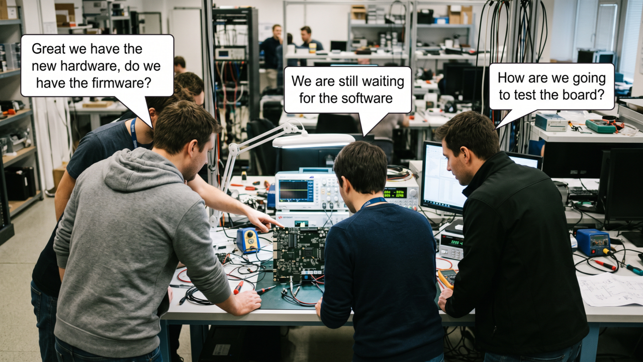
Testing Times - PCB engineers in workshop, testing before firmware
Can You Test a Board Before the Firmware Exists? We were recently asked a very practical question: “Can you test our board using Boundary Scan? The firmware isn’t available yet.” The answer is yes, and this is exactly the kind of situation where Boundary Scan can provide real value. When the first assembled PCBs arrive, hardware engineers want to start establishing confidence in them immediately. Waiting for firmware before meaningful hardware testing can begin creates an unnecessary dependency between two development activities that are often progressing in parallel. The Hardware Often Arrives Before the Firmware This is a familiar situation on many development projects. The first assembled PCBs arrive. The hardware team wants to begin bring-up. But perhaps: The processor firmware is still under development The FPGA image is not yet available Device drivers have not been written The operating system is not running None of this necessarily indicates a problem with the project. Hardware and software development simply progress at different rates. The important question is whether hardware testing has to wait. Boundary Scan Doesn't Depend on Your Application One of the key advantages of Boundary Scan is that the test capability is built into the semiconductor devices themselves. It operates independently of the application software or FPGA design. So the processor does not need to have booted and the FPGA does not need to be configured with the product design before useful structural testing can begin. Boundary Scan can instead be used to gain access to PCB signals through the dedicated test logic already present in suitable devices. That access can help engineers verify things such as: PCB interconnections Address, data and control buses Connections to memories Connections to peripherals Resets, enables and other control signals Accessible interfaces and discrete circuitry The emphasis is primarily on establishing confidence in the connections between the devices and the PCB. Those connections can also be used to exercise part of a non-JTAG device's functionality, providing additional evidence that the surrounding circuitry is behaving correctly. Why That Matters During Bring-Up Suppose the firmware eventually arrives and a memory interface doesn't work. There are now several possibilities. Is there a firmware problem? Is the memory being initialised incorrectly? Is the FPGA or processor configuration wrong? Or is there a physical problem with one of the PCB connections? If structural tests have already established confidence in the relevant hardware, one major area of uncertainty has already been reduced. Instead of the hardware and firmware teams having to work out whose area contains the problem, they have independent evidence to help narrow the investigation. That can make bring-up considerably more systematic. Hardware and Firmware Can Progress in Parallel This is perhaps the broader benefit. Boundary Scan can help decouple initial hardware validation from firmware availability. While the software team continues developing the application, the hardware team can begin verifying accessible areas of the PCB. Then, when the firmware is ready, it starts from a stronger position. Some of the underlying hardware has already been independently checked. That does not remove the need for functional testing. It means functional testing begins with greater confidence in the hardware underneath it. It Helps the Firmware Team Too Firmware engineers are often among the first people to expose hardware problems because their software begins exercising interfaces that may never previously have been used. If a peripheral fails to respond, they can spend considerable time investigating code before discovering that the cause is actually a PCB connectivity problem, an incorrectly fitted component or another hardware issue. Providing the firmware team with boards that have already passed useful structural tests gives them a much better starting point. They can concentrate on developing and debugging the software without automatically becoming the first stage of hardware diagnosis. Start Building Confidence Earlier Functional testing usually needs enough of the system to be operational for the application to run. Boundary Scan works differently. It uses dedicated test logic within the semiconductor devices to provide access to the PCB independently of the application. That means useful hardware testing can begin much earlier in the development process. And when hardware and software teams are both working towards the same deadline, removing unnecessary dependencies between them can be extremely valuable. Closing Thought The question we were asked was: “Can you test the board even though the firmware isn't ready?” Yes. But perhaps the more useful question is: “Why wait for firmware before starting to build confidence in the hardware?” Hardware and firmware development often happen in parallel. The test strategy can too. Boundary Scan provides a way to start checking the PCB earlier, establish confidence in accessible areas of the hardware and reduce uncertainty before the application ever runs. Board Design Tip of the Week When planning a new design, ask what you could verify if no application software were available at all. Can important resets and enables be controlled? Can key interfaces and memory connections be accessed? Can critical signals be driven and observed? Is the JTAG chain readily accessible? Thinking about those questions during the design stage can give the hardware team useful diagnostic capability from the moment the first assembled PCB arrives — rather than from the moment the firmware does. Could boundary scan help you test your next design? Discover how boundary scan can help you improve test coverage, diagnose faults faster and simplify board testing: Find out how XJTAG can help you. Discover more about your board design with the Free XJTAG Layout Viewer. To get started find out how the Free XJTAG Layout Viewer can help you see on your board: Download your Free XJTAG Layout Viewer today