Getting started with your XJLink

XJLink-PF40

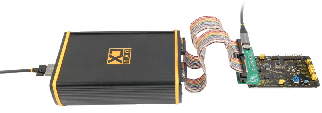
XJTAG XJLink-PF40 test controller connected to demo board

Kit contents


Supplied with XJDeveloper systems (or on request)


To connect your XJLink-PF40 to the XJDemo Board for the installed tutorials:

  1. Connect the locking USB cable between your XJLink-PF40 and your computer.
  2. Plug one end of the twisted pair, rainbow cables into ports A and B of the XJLink-PF40.
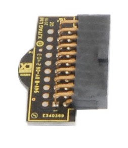
  3. Plug the other end of these cables into the provided adapter as shown above.
  4. The non-locking USB cable is to power the XJDemo Board. Connect this cable to the adaptor board as shown with the other end connected to any USB port that can supply power (this does not need to be on your computer). Plug the adapter into your XJDemo Board as shown.

XJLink-PF20

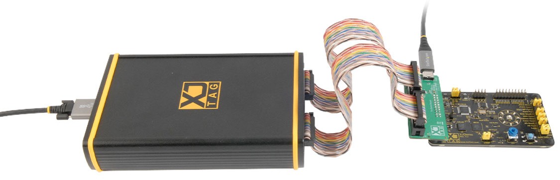
XJTAG XJLink-PF20 test controller connected to demo board

Kit contents


Supplied with XJDeveloper systems (or on request)


To connect your XJLink-PF20 to the XJDemo Board for the installed tutorials:

  1. Connect the locking USB cable between your XJLink-PF20 and your computer.
  2. Plug one end of the twisted pair, rainbow cables into ports A and B of the XJLink-PF20.
  3. Plug the other end of these cables into the provided adapter as shown above.

XJLink2

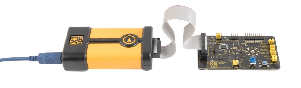
XJTAG XJLink2 test controller connected to demo board

Kit contents

  • 1 x XJLink2 (XRL-0010)
  • 1 x 20-way straight ribbon cable 200mm (0.1”) (CAB-0002)
  • 1 x Blue USB cable (CAB-0009) w/ velcro
  • 1 x XJLink Loopback Board (LBB-0010)
  • 1 x Splitter Signal Integrity Board, Elbow (XJA-0030)
  • 1 x 20-way IDC breakout cable (CAB-0033)


To connect your XJLink2 for the installed tutorials:

  1. Use the blue USB cable to connect the XJLink2 to your computer.
  2. Use the ribbon cable to connect the XJLink2 to the XJDemo Board.

XJQuad

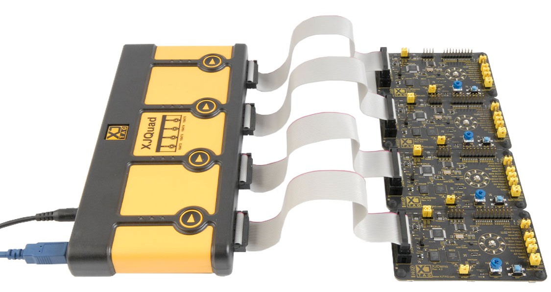
XJTAG XJQuad test controller connected to demo board

Kit contents

  • 1 x XJQuad (XQS-0040)
  • 4 x 20-way straight ribbon cables 200mm (0.1″) (CAB-0002)
  • 1 x Blue USB cable (CAB-0009) w/ velcro
  • 1 x XJLink Loopback Board (LBB-0010)
  • 1 x Power supply, IEC inlet. 2.1mm barrel output, 12V 1.5A (PSS-0000)
  • 1 x 20-way IDC breakout cable (CAB-0033)


To connect your XJQuad for the installed tutorials:

  1. Connect the power cable to XJQuad.
  2. Use the blue USB cable to connect the XJQuad to your computer.
  3. Use the ribbon cable to connect each XJLink to the XJDemo Board. You are provided only 1 demo board but can connect up to 4 of your own boards to the XJQuad as shown above.

PXI-XJLink2

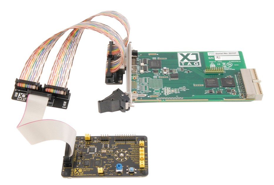
XJTAG PXI-XJLink2 test controller connected to demo board

Kit contents

  • 1 x PXI-XJLink2 (RXX-0030)
  • 2 x 20-way twisted ribbon cables 220mm (0.1″) (CAB-0014)
  • 1 x 20-way straight ribbon cable 200mm (0.1″) (CAB-0002)
  • 1 x XJLink Loopback Board (LBB-0010)
  • 1 x Splitter Signal Integrity Board, PXI (XJA-0032)
  • 1 x Splitter/Combiner Signal Integrity Board, Standard (XJA-0033)
  • 1 x 20-way IDC breakout cable (CAB-0033)


To connect your PXI-XJLink2 for the installed tutorials:

  1. Plug in the two twisted pair, rainbow cables to the adapter attached to the PXI-XJLink2 board.
  2. Plug in the two twisted pair, rainbow cables to the two connectors on the side of the provided Splitter/Combiner Signal Integrity Board, as shown above.
  3. Plug in the ribbon cable to the side with one connector.
  4. Plug in the other side of the straight ribbon cable to your board as shown above.