Non-Standard Cell Types in BSDL Files
Introduction
The IEEE Std. 1149.1 set of standards define the Boundary Scan Description Language (BSDL). The language describes the testability features of components which comply with the IEEE 1149.1 standards. This BSDL file is required for every compliant component before JTAG test tools can use their test features. BSDL is related to the VHSIC Hardware Description Language (VHDL) (IEEE Std 1076) and describes, among other things, the type of boundary scan cell associated with each pin on the device. Standard cell types are described in a VHDL package (for example STD_1149_1_2001) which allows them to be supported automatically by the XJTAG BSDL parser.
Standard defined boundary cell types are BC_0, BC_1 … BC_10 (and in 1149.6-compliant devices AC_0 to AC_10). Sometimes, however, manufacturers of IEEE Std. 1149.1 compliant devices may be required (or wish) to use cell type variants that are not included in these ‘standard’ types. In this case, additional cell type definition information is required.
This page describes how to identify such devices and how the additional information should be made available for XJTAG system to interpret these ‘non-standard’ cell types correctly.
Additions to the BSDL File
Every BSDL file uses a standard cell type package which defines which version of the IEEE Std. 1149.1 it implements. The most common package at present is STD_1149_1_2001, but older components may refer to earlier standard packages such as STD_1149_1_1994. The reference to the package will be contained within the component entity declaration block as a use statement, as shown in the following abbreviated example of a typical BSDL file entity:
entity COMPONENT_NAME is
	-- Generic definitions and default assignments
	generic...
	-- Port declarations
	port (
		...declarations...
	);
	-- Standard pin-type package use clause
	use STD_1149_1_1994.all;
	-- Miscellaneous constants and attributes
	constant...
	attribute ...
	attribute ...
	... etc ...
end COMPONENT_NAME;
If additional definitions or non-standard boundary scan cell types are incorporated into the component, their definitions are usually supplied by the manufacturer in a separate ‘package’ file and an additional use statement will be included in the BSDL file entity declaration. For example, the following line could be added to the BSDL file to show that the MY_PACKAGE_NAME package is needed for BSDL analysis.
use MY_PACKAGE_NAME.all;
Identifying when additional BSDL package files may be required
If you assign a BSDL file which requires an additional package file to a device, XJTAG will display an error, e.g.:
3032at44.bsd: Missing cell types: IO
Supplying Additional BSDL Package Files in XJDeveloper
To correct the error shown in the previous example, you need to find the referenced package file. This will usually be available on the component manufacturer’s website and a copy should be saved in the same directory as the component’s BSDL file.
On the JTAG chain screen, double-click the device in question, to display the Configure JTAG Device dialog.
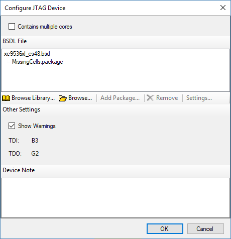
Select the BSDL file name in this dialog and then click the Add Package… button to add a package file. Multiple package files can be added if required.
Dealing with Custom BSDL Package Files in XJAnalyser
The above solution provides the ability to specify additional BSDL packages for XJEase projects. However, this will not work for projects created in standalone XJAnalyser unless they have been imported by XJDeveloper.
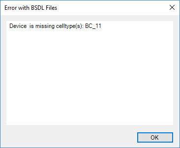
Using BSDL files in standalone XJAnalyser projects currently gives no mechanism for including supplementary BSDL package files. Attempting to use the BSDL file in this case will produce an error similar to that shown below when the BSDL parser attempts to process the undefined IO cell type.
There are two ways to use XJAnalyser in this case.
- The first way is to circumvent the error by not selecting a BSDL file for this device (uncheck the “Use BSDL file” checkbox) thus forcing XJAnalyser to place the device into BYPASS mode. XJAnalyser will then continue to operate as normal but no monitoring or control of any of the pins on this device will be possible.
- The second way is to manually include the supplementary BSDL package file within the BSDL source file by using a text editor to copy its entire contents into the BSDL file in place of the use statement as shown in the following example. This will allow XJAnalyser to use all the features of the device, and from then on there will be no need to include the package file when using the BSDL file in XJDeveloper projects. However remember that if you ever replace the BSDL file with an updated version it will be necessary to modify the new file in the same manner.
To modify the BSDL file look for the use statement which defines the package file to be included and replace this statement with the entire contents of the package file using cut and paste within your text editor. Be careful not to replace the use statement for the standard package file STD_1149_1_XXXX as this will still be required.
For example:
...
use STD_1149_1_1994.all;
use MY_PACKAGE_NAME.all;
attribute PIN_MAP of COMPONENT_NAME : entity is PHYSICAL_PIN_MAP;
...
should be replaced by:
...
use STD_1149_1_1994.all;
package MY_PACKAGE_NAME  is
	constant IO : CELL_INFO;
end MY_PACKAGE_NAME;
package body MY_PACKAGE_NAME is
	constant IO : CELL_INFO :=
	((BIDIR_IN, EXTEST, PI),
	(BIDIR_IN, SAMPLE, PI),
	(BIDIR_IN, INTEST, PO),
	(BIDIR_OUT, EXTEST, PO),
	(BIDIR_OUT, SAMPLE, PO),
	(BIDIR_OUT, INTEST, PI));
end MY_PACKAGE_NAME;
attribute PIN_MAP of COMPONENT_NAME : entity is PHYSICAL_PIN_MAP;
...
An example of how to do this is contained in the following custom-bsdl-example.zip file which contains the original and modified versions of the BSDL file for a Philips SAA7113 device, as well as the associated package file.